Although this blog is mostly about my trials and tribulations with Revit, my experience with BIM software started many years before Revit was even dreamed of. There have been many forerunners to the current crop of BIM programs, and I had the privilege of working with two of them, which I would like to talk about lest they become forgotten in the mists of BIM history.
The term BIM is an acronym for Building Information Modeling - that means creating a 3D geometric model that has non-geometric data attached to it. Of course any BIM program needs to have meaningful ways of representing and extracting information, such as drawings, visualisations, schedules etc.
I also worked with quite a few 3D modeling programs (Computervision, Caddsman, Sketchup, Mac Perspective, MicroStation etc) - but they lacked meaningful "information" as part of the model. I did try to use "Triforma" (The BIM version of MicroStation), but gave up on that and resorted to using MicroStation as a documentation system (which it was very good at) with a bit of 3D modeling thrown in.
Caddsman Architect was a really great Australian 3D modeling/documentation program, but it did not integrate well with other systems, and with so few other users out there, training was an ongoing burden.
My first experience with BIM, back in 1981, was using "SCRIBE", which was a 3D modeling and thermal analysis program written by Cedric Green at Sheffield University - more about that in another post. That was followed by a couple of years of manual drafting with pen and/or pencil, followed by a stint of 3D modeling with Computervision at DP Architects in Singapore.
In 1985 I started work using RUCAPS at HKPA Architects in London - this really was a precusor to modern BIM programs. Although it technically worked in 2.5D we were able to create 3D views, 2D drawings and details; it also had the capability to attach rudimentary information - and it did allow basic scheduling of components and quantities (after a fashion). Although some might dispute the use of the word "Information" for RUCAPS, I maintain that it did happen. Of course it was superseded by such products as Sonata. All of this is documented elsewhere - on Wikipedia and various articles here and there.
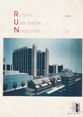
RUN - RUCAPS User Group Newsletter
One of the good things I found about RUCAPS was the strength of the User Group, particularly in the UK and Australia - they had regular meetings and a newsletter that evolved into an international magazine. I became involved in the user group and with running the newsletter (RUN) - first as a technical editor, and later as overall editor.
The earliest edition I have found reference to was RUN 3 in November 1984 - so I'm guessing the first edition was early 1984. My involvement started with writing many articles, particularly from 1987 (RUN 11) onwards. When I joined as technical editor, the overall editor was Andrew Postlethwaite (of Shepherd Robson Architects); the overall coordinator and marketing consultant was Jo Hunting (of t² Ltd) - she made it all happen.
A DECADE OF RUCAPS
ln 1972 when GMW Portnership visited the Liverpool Centre for Computer Aided Building Design to see 'Neanderthal' RUCAPS, a 1 Megobyte disk drive, stood 5 feet high by 4 feet deep by 2 feet wide. lt needed its own three phase electricol supply. could never be switched off ond never worked continuously for more thon a couple of weeks; but in those days you didn't let little things like that deter you!
By the time thot RUCAPS was first sold in 1977 you could fit 2.4 Megobytes of cartridge disc into a cabinet 9 inches high by 3 feet deep by 2 feet wide. These discs were highly reliable despite the fact that the whole cabinet shook when you tried a complex zoom.
At that time none of us were aware that we had seen the beginning of a technological revolution whlch would continue to gather momentum, just os I suppose Cro-Magnon man would not have expected his offspring to land on the moon.
By taking a last look bock at the past ten years of RUCAPS perhops we can find some a useful pointers to the next ten yeors of development.
The first RUCAPS systems were single user systems which ran on the most popular mini-computer of its day - a Digital PDPI I /34. This machine, like most powerful mini-computers of its time, was a l6-bit
computer. The discs, as I have said, were 2.4 Megabyte removable cartridge - the top one containing the RUCAPS software and the bottom one containing your project data. The screen which was also
monufoctured by Digital was an 11 inch refreshed vector disploy which did not have any memory of its own instead it used the computer's memory to store its on screen display data. This created a strong conflict for computer memory when you realise that the maximum capacity of the PDPI 1/34 was
only 64 Kilobytes in total. (For those of you who are too young to remember what Kilobytes are, then 64 kilobytes is one sixteenth of 1 Megabyte.) Every imaginoble trick to save memory had to be
employed but still the moximum number of components displayable on the VT-11 was just 50.
Todoy we might consider such a system for a small house extension, but remember that in 1977 these systems were used to produce production drawings on 400 bed hospitals, large factories and the University of Riyadh. Without SKETCH, DRWCAT, LAYOUT, COMGEN, AUTOPROD or IMAGER
and many more. the four users displayed ingenuity and tenacity where today we demand function and ease of use. But, of course, it is thanks to the successes of these pioneering users that RUCAPS has been able to develop to use modern intelligent screens and powerfuI multi-user computers.
Today, when we are constantly being made aware that we live in a time of rapid technological development, it is hard to comprehend that this was not always obvious to us, But before we begin to be
complacent, sitting in front of our Concept ond Designer workstations, who among us today can conceive of a workstation (ten yeors hence) with 80 times the capacity, or who can imogine what sort of building we will be designing on a RUCAPS system with 20 times the program at our disposal? A
fascinating thought I hope, with which to enter the second decade of RUCAPS development.
DR JOHN DAVISON
RUN 15 (mid 1988) saw the introduction of Sonata, which was written by Jonathan Ingram and Murray Pearson (ex-t²). It was then bought by t² Solutions, initially to run alongside RUCAPS - but ultimately all resources were put into the development of Sonata. This edition included the first of many articles about Sonata:
More to follow on subsequent issues of RUN . . . .


